Introduction
Recently, I had the opportunity to collaborate with a university research lab to build some vapor sensors to roughly measure ethanol (EtOH) vapor within an operant chamber. This project was a lot of fun.
With extremely limited circuit documentation on the web and never having personally used Arduino before, there were a lot of interesting hiccups I ran into. Overall, this project was a bit out of my wheelhouse, but with much determination, the finished product turned out rather nicely.
This project was made possible and open-source by the work of Dr. Brian McCool. The Arduino code hosted on GitHub, the general project design (along with most of the corresponding recommended parts list), and the conceptual use of the project for alcohol research are his work.
The Lab
This project was completed for the Reward and Addictive Disorders (RAD) Lab at Miami University by Dr. Anna Radke.
The sensors will be used in a current experiment utilizing mouse operant chambers for a visual representation of the EtOH vapor pressure in the chambers. The support of this experiment utilizing these modules is under the direction of Elizabeth Sneddon (PhD candidate at the time of this writing; recipient of the prestigious DSPAN F99/K00 from NINDS – read more from the Lab News here).
I highly recommend checking out the RAD Lab’s website for more information on Dr. Radke and both her incredibly talented graduate students and undergraduate students. You can find information about many of their current projects.
Shameless plug: You can also check out a paper from the RAD Lab of which I am an author: https://pubmed.ncbi.nlm.nih.gov/30431655/
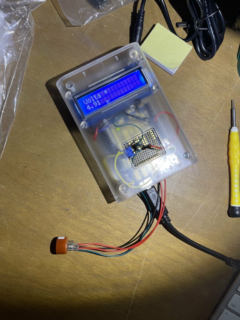
First Successful Unit
The Parts
Per Module Quick List:
- Arduino Uno R3
- Arduino Proto Shield for Arduino Kit (Stackable)
- Clear Enclosure for Arduino (adafruit.com)
- Standard LCD 16x2 screen (adafruit.com version) (amazon.com pre-soldered jumpers)
- i2c/SPI character LCD backpack
- MQ-3 alcohol gas sensor (sparkfun.com)
- Power supply (see comments below)
- Standard USB printer cable
- 500Ohm Trim Potentiometer (for rat operant boxes); 1k-2kOhm Trim Potentiometer (for mouse operant boxes) – this kit contains 4 of each along with other (unnecessary for this project) resistance values
- Wiring: while there are many options for wires, this kit has an assortment of Male-Female, Male-Male, and Female-Female wires that will be helpful in learning/testing the circuit later
- Optional: Breadboard (this is super helpful to learn/test the circuit before you commit to soldering, but it is definitely not a requirement)
- Optional: This project REQUIRES soldering. I used this soldering iron kit here. In addition to this soldering iron, a solder sucker kit is highly recommended when you make a mistake.
Power supply notes: For the power supply, you can theoretically use a 5V 2A power supply, but I did not have luck with this option. For some reason, the voltage would drop to 3V on the Arduino unit when powered via this method. 3V is insufficient to run the readout on the screen, and I did not end up using this method for the finished product. If you want to test for yourself or know of some way to make this work, you could consider this 5V 2A switching power supply.
Otherwise, I highly recommend powering your Arduino unit with a standard USB printer cable and a USB power block. Your mileage with that particular power block may vary, as it is specifically 5V and 2.1A. I did not use this particular power block but instead used an Apple power block for an iPhone. Any block that supplies at minimum 5V and 2A should be sufficient.
Nonetheless, you will need at least one standard USB printer cable in order to transfer the program to the Arduino device for the readout. This is covered in the Programming section.
This list is adapted from a list shared by Dr. Brian McCool.
As an Amazon Associate, I earn from qualifying purchases. Thank you for supporting the maintenance of this blog. The pricing will be the same for you regardless if you use my links or not! Thanks for your support!
The Circuit
This circuit diagram was drawn by my father, a radio and broadcast engineer, and I am very appreciative of his work and direction with this particular project. Hopefully this drawing can be useful to you or a technically-inclined student in your lab. Drawn by RW 09/04/2021
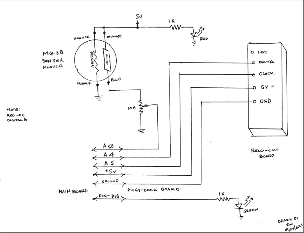
Arduino with MQ-3B Sensor Module Wiring Diagram
See or download the diagram here https://drive.google.com/file/d/1gVgyCg9lm8LaurHVQtRFqXGifgDlCiEb/view?usp=sharing OR here https://github.com/RobertDWhite/arduino_mq-3b
Assembling the Arduino
The order of completing these steps does not necessarily matter, but this is the order I completed them.
I am certainly no Arduino expert. In fact, this project was my first experience with Arduino. I definitely had a fun (sometimes irritating) time building the modules. Unfortunately, I did not take as many pictures as I should have of the process or the built circuit (mostly because I did not intend to write this up). If I have an opportunity to build more in the future, I will update this post with more / better pictures.
Preparing the Protoshield and Connecting to the Mainboard
Assembling the Protoshield will require some soldering. You will see the many components included with the Protoshield nearly immediately. These components should be assembled to look like the image below. Specifically not the location of the capacitors, resistors, switches/buttons, and LEDs. The components can be soldered from the bottom of the board.
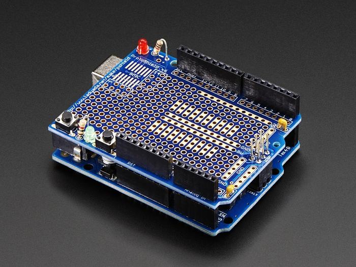
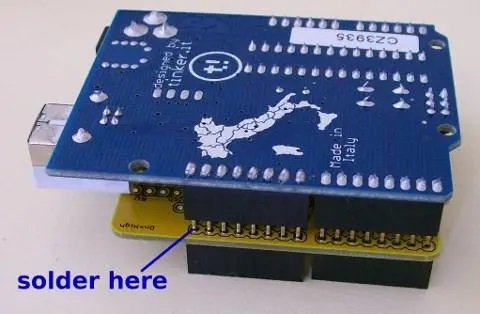
The black pinouts should be matched and aligned as shown in the picture above as well. Those should also be soldered from the bottom (see picture below for clarity), and they will be used to align the Protoshield to the Mainboard. The pins soldered to the Protoshield will insert into the pinouts on the Mainboard.
Once complete, your Protoshield and Mainboard should look like the first image above.
Connect the LCD Backpack to the LCD Screen
The 16-pin connector will be used to connect the backpack to the screen. The front of the screen should be soldered using the short ends of the connectors (see image below). Solder all 16-pins.
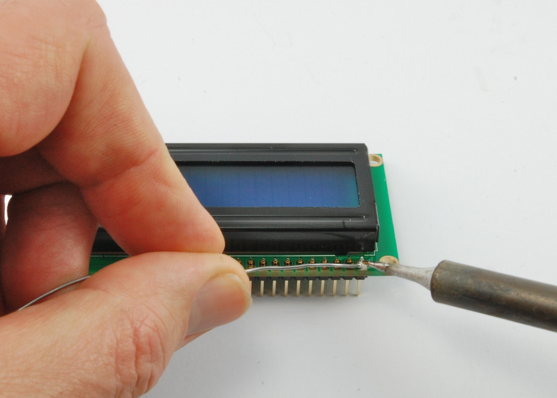
Protip: Attach the 5-screw pins to the backpack before continuing. Once the backpack is attached to the screen, adding the screw pins is very very difficult.
From the other side, attach the backpack and solder all 16-pins as shown in the image below.
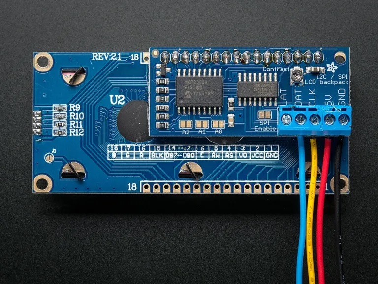
The GND, 5V, CLK, and DAT ports are shown on the Diagram as the READ-OUT BOARD.
Wire the Protoshield
Unfortunately, I do not have too many detailed images of the Protoshield with the wires attached. In the image below, you can see how I wired the 5V and the Ground from the Mainboard to the central 5V and GND. From there, all the required 5V and Ground wires can be soldered to the center for easy access.
When wiring, I recommend using one of the breadboards listed as optional in the parts list. As you can see in the image below, you can test your wiring before making it more permanent with solder. Some parts can and should still be soldered (e.g., the screen and the backpack), but you will not regret testing the wiring before committing to solder.
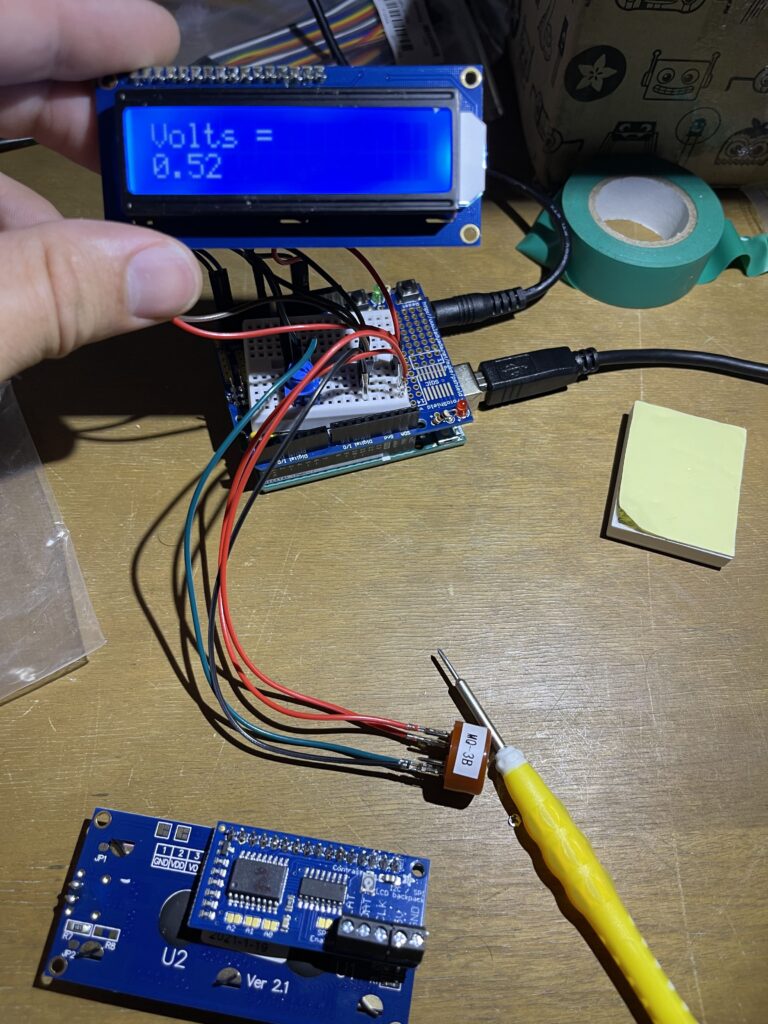
Successful Test Readout with Breadboard
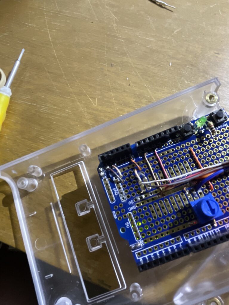
Cleaned Up Wiring
Programming
The code provided at GitHub was provided by Dr. McCool. Download the code to your computer. I highly recommend this post on how to upload the code to your Arduino. Once you have the connections as described above with your uploaded program to the Arduino, your screen should read-out the voltage.
Fine-Tuning the Read-Out
The backpack has a small circular potentiometer built onto it near the top-right corner. The potentiometer is labeled “Contrast.” If your screen lights up but you do not see a read-out, you may need to turn the potentiometer to adjust the contrast on the screen. I had to adjust the contrast on each one of the modules I assembled.
Caution: As shown in the image below, the potentiometer was easily displaced and broken. Be very careful when turning the potentiometer so you do not experience the same dilemma I did. This required a complete rewire for this particular module with a new external potentiometer to adjust contrast. I do not have a wiring schematic to share for this at this time, and if you happen to break the potentiometer, I recommend just getting a new backpack.
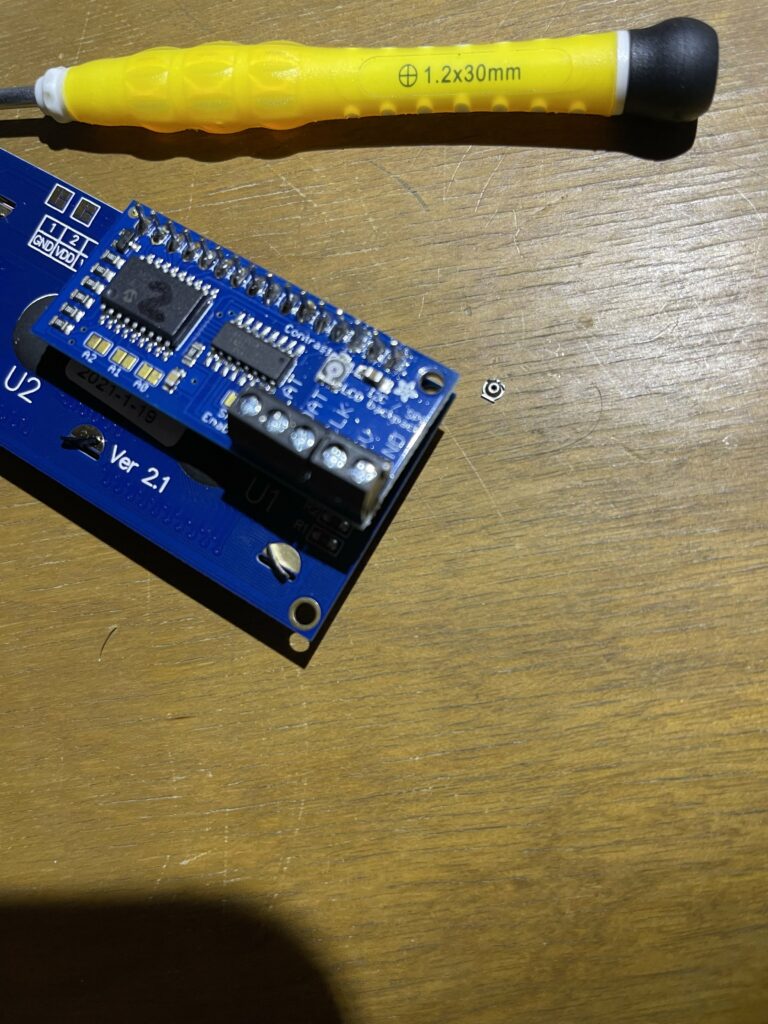
Broken Backpack Potentiometer
Wrapping Up
Congratulations if you made it this far and everything is working! I hope this tutorial aids you in your endeavors and can be a positive contribution to your research or personal projects.
As always, if you have any questions, feel free to start a Discussion on GitHub, submit a GitHub PR to recommend changes/fixes in the article, or reach out to me directly at [email protected].
Thanks for reading!
Robert
First Successful Unit
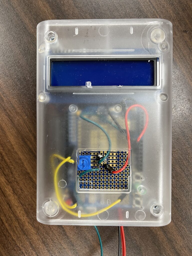
First Completed Unit
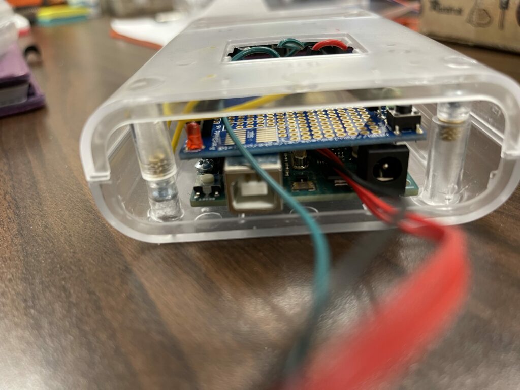
Undershot of a Successful Build